Brand Sort:
OMRON
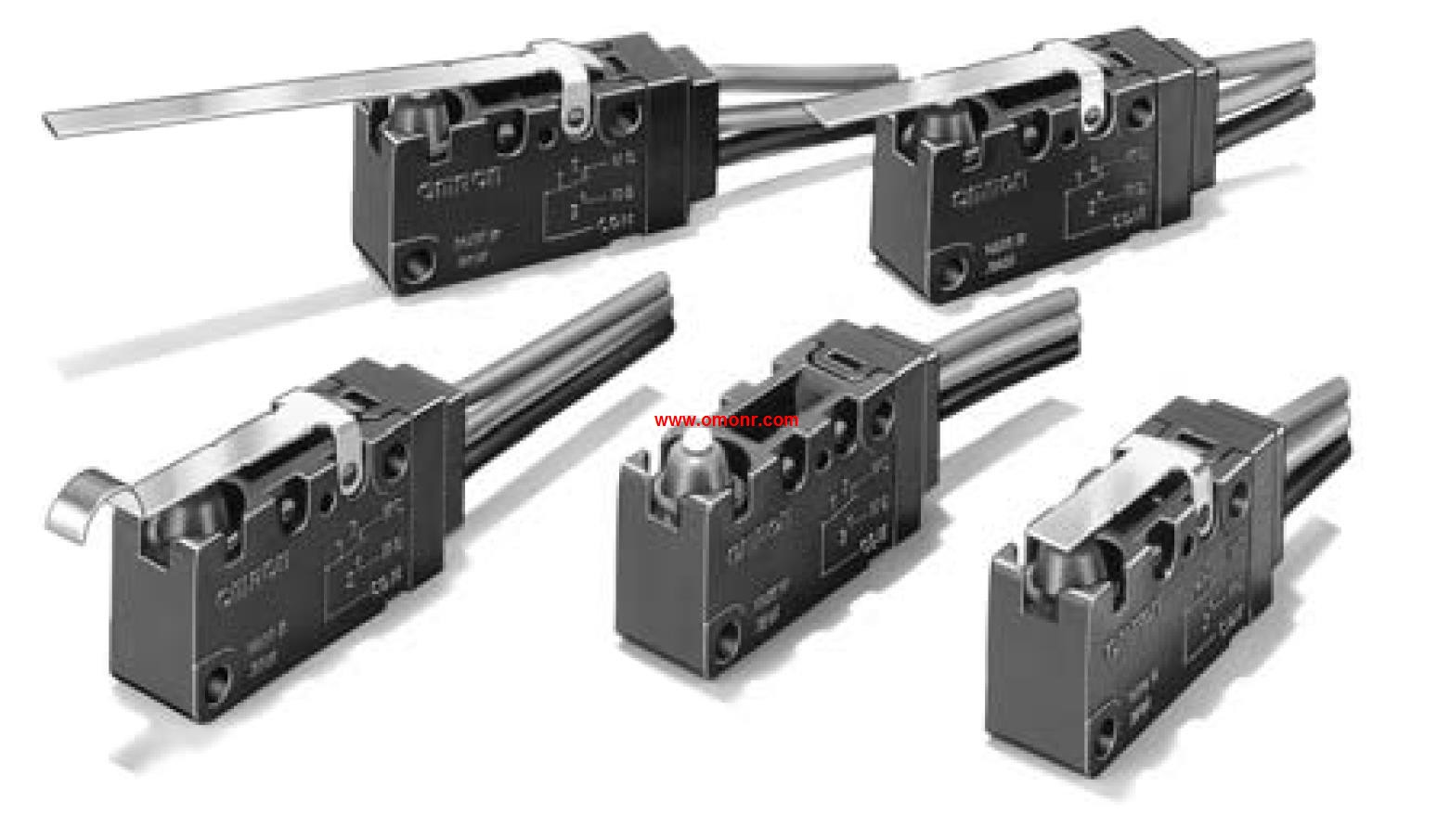
OMRON D2SW-01L2T Price
- Brand: OMRON
- Country: JAPAN
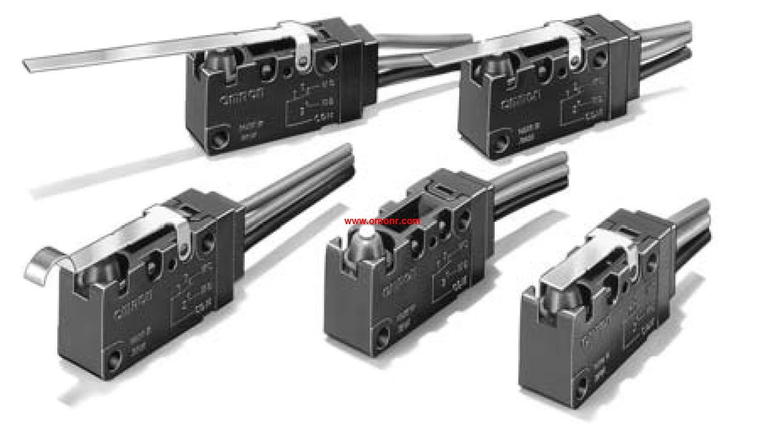
- Name: Sealed Subminiature Basic Switch
- Model: D2SW-01L2T
- Price: U.S.$ 8.44
OMRON D2SW-01L2T
Classification: Exclusive Models.
Description: Crimping terminals.
Temperature range (See note 3.): 0°C to 300°C.
Element type: K (CA) J (IC).
Conductor type: Grounded type.
Class: 2 (0.75).
Protective tubing material: --.
Terminal type: Exposed lead wires.
Page: 21.
A Wide Variety of High-precision.
Temperature Sensors.
Previous models with M3 screw connections have been joined,
by new models with ferrules to help reduce wiring work D2SW-01L2T
Ideal for the thermal input devices of Temperature Controllers.
Select from a wide variety of Temperature Sensors according,
to the temperature to be measured, location, and environment,
and also according to the type and shape of the terminal. Contact type: Microload (125 VAC, 0.1 A; 30 VDC 0.1 A).
Operation: Momentary operation (Self-resetting).
Output: SPDT.
Lighting: Incandescent lamp, 14 VAC/VDC.
Operation Unit color symbol: Enter the desired color symbol for the Pushbutton,
in @. R (Red); Y (Yellow); G (Green); A (Blue); W (White).
Pushbutton Switch Series with.
Square 40-mm Body.
Combines miniature design with distinct but soft sense of operation.
Easy panel mounting from the front and simple lamp replacement.
without tools. Type: square.
Screen mode: no segmentation.
Light way: incandescent lamp.
Power supply voltage: 14V.
Operation Department color: yellow.
Square 40mm body of the indicator light series.
The same type as the A3S series button switch.
Easy to install from the front panel and no tools to carry out the lamp replacement. Time specification: Instantaneous type.
Current setting range: 50 to 160 A.
Operating voltage: 200/220/240 VAC.
Resetting method: Manual.
Solid-state Relay Enables Choice of Three.
Operating Functions (Overcurrent, Open,
phase, and Reverse-phase).
Protects 3-phase induction motors and their loads from damage.
Selection and combination of operating functions from overcur,
rent, open-phase, and reverse-phase.
Circuit and output relay operation can be checked by just operat,
ing the test button.
The set time value can be checked easily because operation time,
is indicated from the start of operation.
Space-saving, integrated construction.
Note: If the K2CM is used with an inverter, the operating conditions will,
depend on the load wiring length, inverter carrier frequency, basic,
frequency, and load conditions. Error will occur in the operating,
values of the overload elements. It is recommended to test operation,
D2SW-01L2T Operation manual/Instructions/Model selection sample download link: /searchDownload.html?Search=D2SW-01L2T&select=5
...more relevant model market price >>>>
Related products
OMRON
Sealed Subminiature Basic Switch
D2SW-01L2H
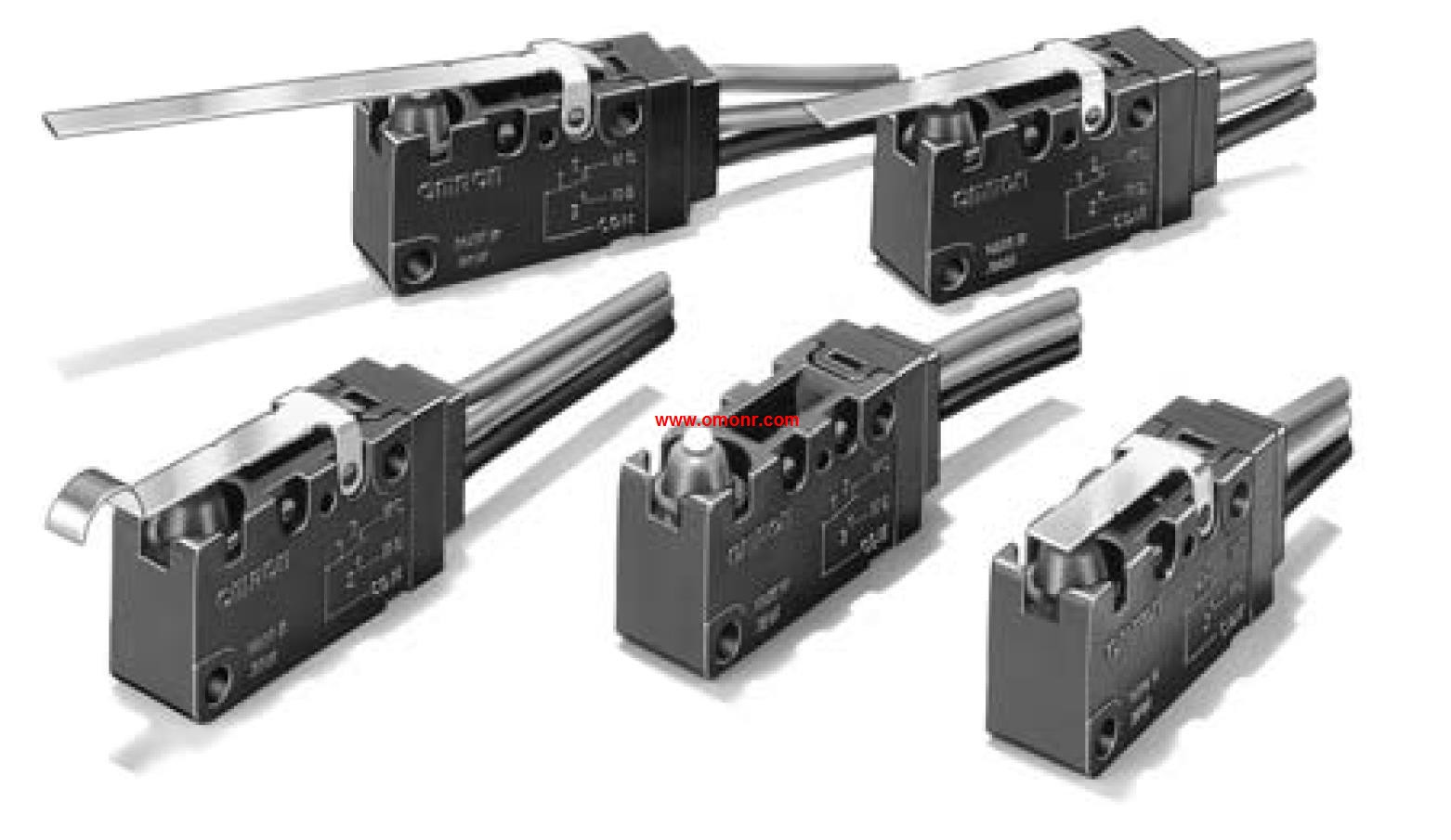
Ratings: 0.1 A.
Actuator: Hinge roller
OMRON
Sealed Subminiature Basic Switch
D2SW-3L1M
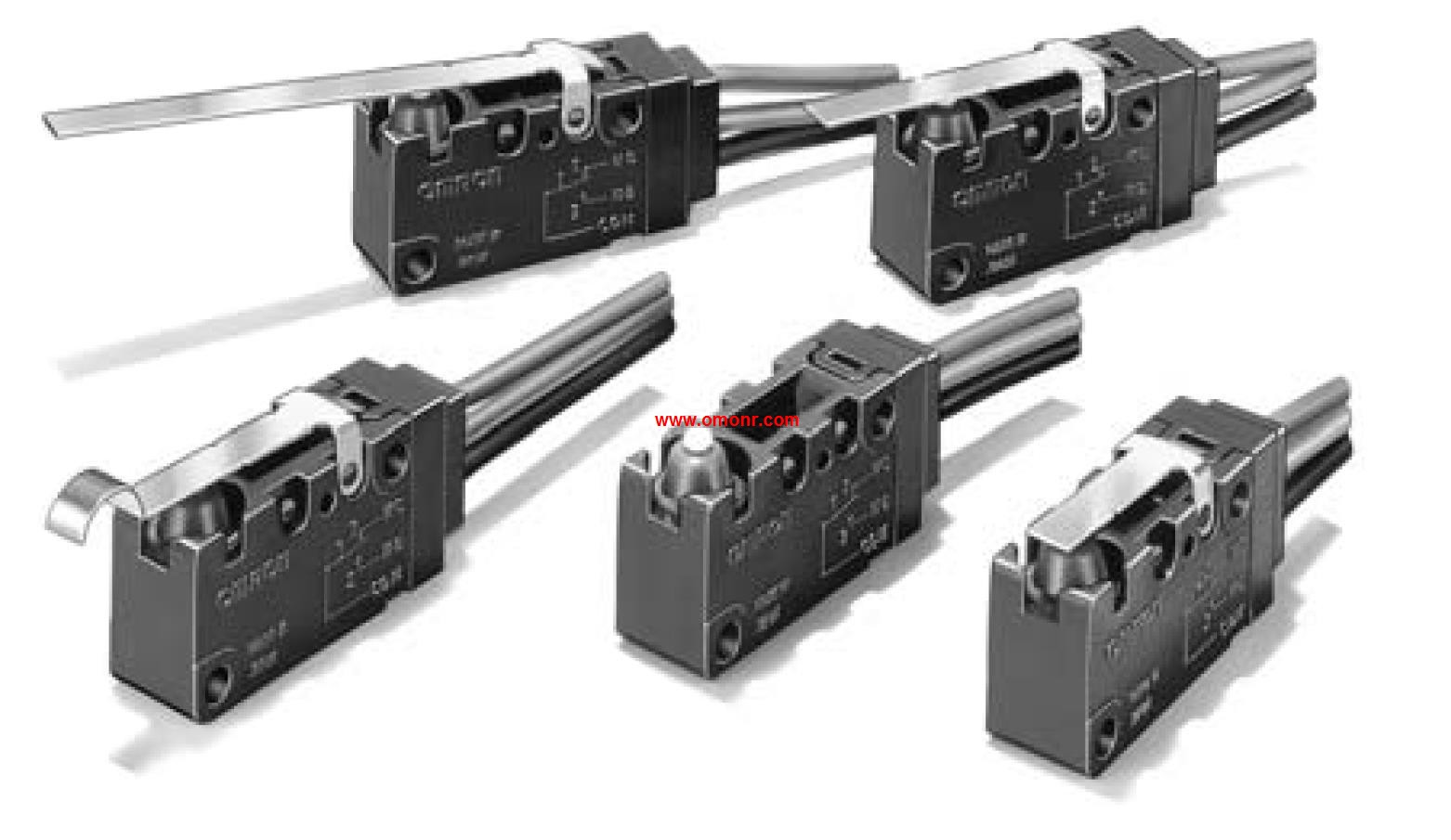
Ratings: 3 A.
Actuator: Hinge lever.
T
OMRON
Sealed Subminiature Basic Switch
D2SW-01L1H
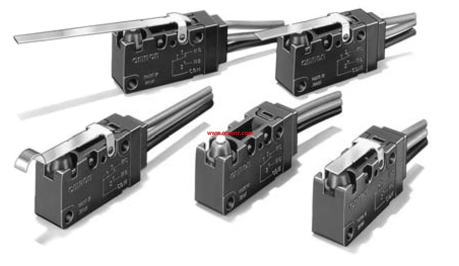
Ratings: 0.1 A.
Actuator: Hinge lever.
OMRON
Sealed Subminiature Basic Switch
D2SW-3L3D
Ratings: 3 A.
Actuator: Simulated rolle

