Brand Sort:
OMRON
OMRON XS3H-M421-401-R Price
- Brand: OMRON
- Country: JAPAN
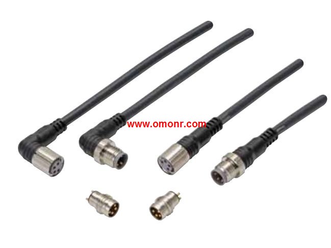
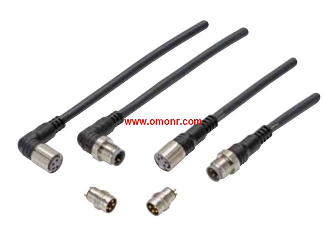
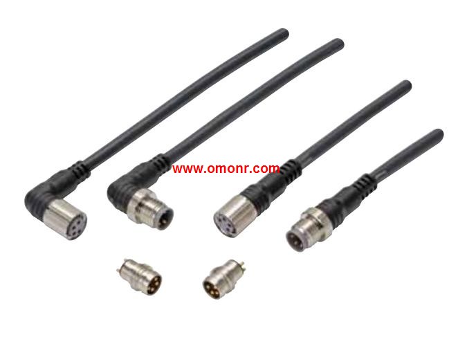
- Name: Round Water-resistant Connectors
- Model: XS3H-M421-401-R
- Price: U.S.$ 26.26
OMRON XS3H-M421-401-R
Isolation: Photocoupler.
Zero cross function: Yes.
Indicator: Yes(Yellow).
Applicable output load (See note 1.): 10 A at 5 to 200 VDC.
Rated input voltage: 5 to 24 VDC.
Wide Lineup of General-purpose Solid State.
Relays with Applicable Loads of 5 to 90 A.
AC Output Relays with 75-A and 90-A output currents have been,
added to the G3NA Series.
All models feature the same compact dimensions to provide a,
uniform mounting pitch XS3H-M421-401-R
Built-in varistor effectively absorbs external surges.
(except G3NA-D210B).
Operation indicator enables monitoring operation.
Protective cover for greater safety.
Standard models certified by UL and CSA and -UTU models by TÜV.
(except G3NA-410B, G3NA-420B, and G3NA-440B(-2)). Input capacity: 16 points.
Internal I/O common: NPN.
ON voltage: 15 VDC min.
(between each input terminal and the V terminal)
OFF voltage: 5 VDC max.
(between each input terminal and the V terminal)
OFF current: 1.0 mA max.
Input current: 6.0 mA max./input (at 24-VDC),
3.0 mA min./input (at 17-VDC).
ON delay: 0.1 ms max.
OFF delay: 0.2 ms max.
Input filter value: Without filter, 0.5 ms, 1 ms,
2 ms, 4 ms, 8 ms, 16 ms, 32 ms. (Default setting: 1 ms)
Number of circuits per common: 8 points/common.
Input indicators: LED display (yellow).
Isolation method: Photocoupler isolation.
I/O power supply method: Supply by I/O power supply.
Input device supply current: 100 mA/point.
Unit power supply current consumption: 90 mA max.
(for 20.4 to 26.4-VDC power supply voltage)
I/O power supply current consumption: 5 mA max.
(for 20.4 to 26.4-VDC power supply voltage)
Weight: 370 g max.
Expansion functions: No.
Short-circuit protection function: No.
A common terminal is provided for each contact.
It eliminate the needs for relay terminal blocks.
It is unnecessary to share the common terminal,
among multiple contacts.
Easy-to-find wiring locations.
Detachable screw terminal block facilitates the maintenance.
Input response time can be switched for high-speed processing.
Selectable node address setting methods: setting with rotary,
switch and with tool software.
When setting the nodes with rotary switch, setting is easy and,
node identification becomes possible for maintenance.
XS3H-M421-401-R Operation manual/Instructions/Model selection sample download link: /searchDownload.html?Search=XS3H-M421-401-R&select=5
...more relevant model market price >>>>
Related products
OMRON
Round Water-resistant Connectors
XS3H-M421-401-R

No. of cale cores: 4.
Cale connection
OMRON
Round Water-resistant Connectors
XS3W-S421-401-R

No. of cale cores: 4.
Cale connection
OMRON
Round Water-resistant Connectors
XS3H-S421-401-R

No. of cale cores: 4.
Cale connection
OMRON
Round Water-resistant Connectors
XS3H-M421-4C3-R

No. of cale cores: 4.
Cale connection
